Self-sustaining circuit using P-channel MOSFET

The circuit below shows a simple but effective way to power activate a (DC) device by pressing a button. The device can be completly switched of electronically (e.g. by a microcontroller). (Switch SW2 if only shown to demonstrate the operation principle of the circuit.)

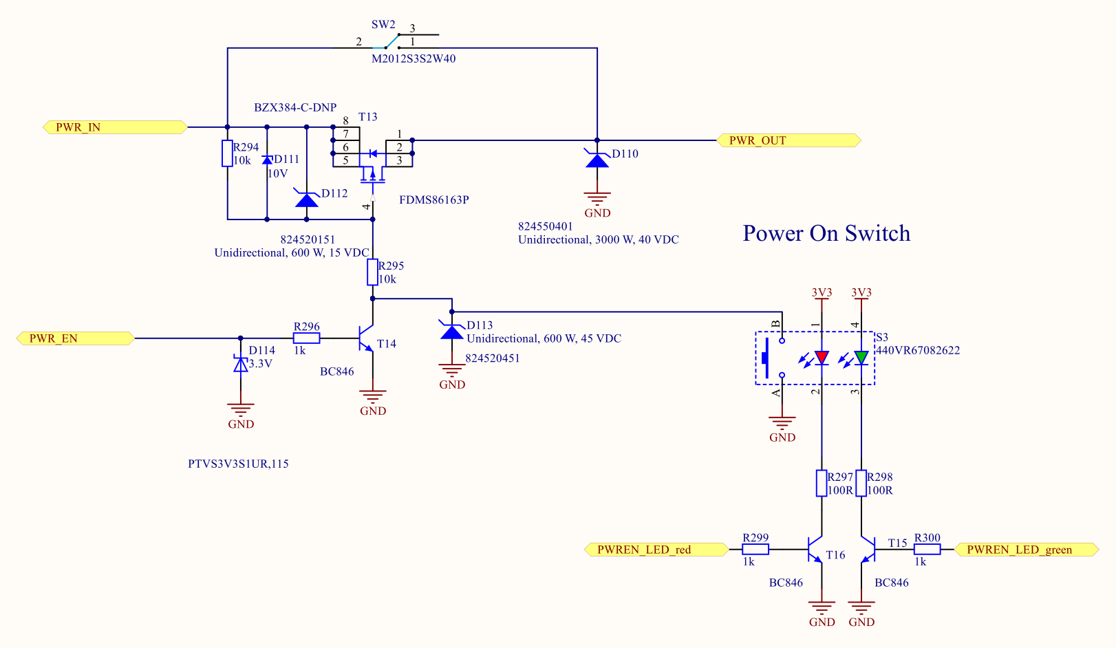
Depending on the selected P-channel MOSFET T13 the circuit can handle voltages bigger of more than 60V and currents of several tens of amperes.

The same functionality could be achieved by a relay at the expense of volume (relay is much bigger) and power consumption (~100mW or more). Especially in a battery powered portable application, there is no way for a relay.

Circuit description

Power enters the schematic at the PWR_IN port (top left). In OFF-state the MOSFET handling the power (T13) is blocking current from its source to drain. Please note the body diode of the MOSFET is in reverse to the current flowing from PWR_IN to PWR_OUT when MOSFET is conducting. In the OFF-State the gate of T13 is pulled to the PWR_IN voltage level via pull-up resistor R294 thus keeping the MOSFET not conducting. The value of R294 is selected to keep safe operation at minimal losses when the gate is pulled low.

To activate the device the user will press the activation switch S3 which closes the contacts A-B and pulling the gate of T13 to GND. As soon as the gate-source voltage at the gate of the MOSFET drops below Vgs_th (threshold voltage see the datasheet of your preferred MOSFET) T13 will start conducting. As current flows from PWR_IN to PWR_OUT a microcontroller connected to PWR_EN can boot and then control the bipolar NPN transistor T14 which will pull the gate towards GND, too. As the microcontroller starts to work it immediately needs to output high level (3,3V or 5V) to T14. After this, the button can be released by the user. The sequence to power a microcontroller should take less than 1ms.

Remaining components are mostly protecting the MOSFET and the microcontroller pin. One big problem with this kind of circuit is the limited gate-source voltage of most modern MOSFET. The majority of them will take permanent damage if the gate-source voltage (Vgs) is bigger than (-)20V. If you want to use this circuit in a 24V or even 48V environment Vgs needs to be limited. This is done by the zener diode D111. Across D111 there is a constant voltage drop of the zener voltage (chosen to be 10V here). At this voltage, Vgs is big enough to keep T13 fully conducting. D111 forms a voltage divider in conjunction with R295. TVS diodes D110 and D112 further protect T13 against voltage transients and act as a basic over voltage circuit (requiring a fuse elsewhere before this circuit!). D113 is used to protect the bipolar NPN transistor T14 in the case of an overvoltage event. R296 acts as current limiting resistor into T14 in order to limit the current out of the microcontroller pin. For T14 any NPN (e.g. BC817, BC547, BC548, …) should be fine. TVS diode D114 limits the current in case of a failure at the MOSFET (low impedance failure MOSFET conducting input voltage to its gate).

In order to switch the device OFF the microcontroller needs to deactivate its output pin (switch to lo-state). As a consequence, T14 stops pulling the gate of T13 to GND. The gate is charged again to input-level voltage (via pull-up resistor R294). T13 stops conducting, the circuit’s power supply is cut off and so is the microcontroller. Nearly no current is consumed by this circuit in OFF-state.

Simplification for lower voltage

If you have a supply voltage which is lower than the maximum gate-source voltage (Vgs_max) of your selected MOSFET (T13 above) there is no need for the MOSFET driver (T14), the voltage divider and zener diodes. This might be useful at USB designs etc.

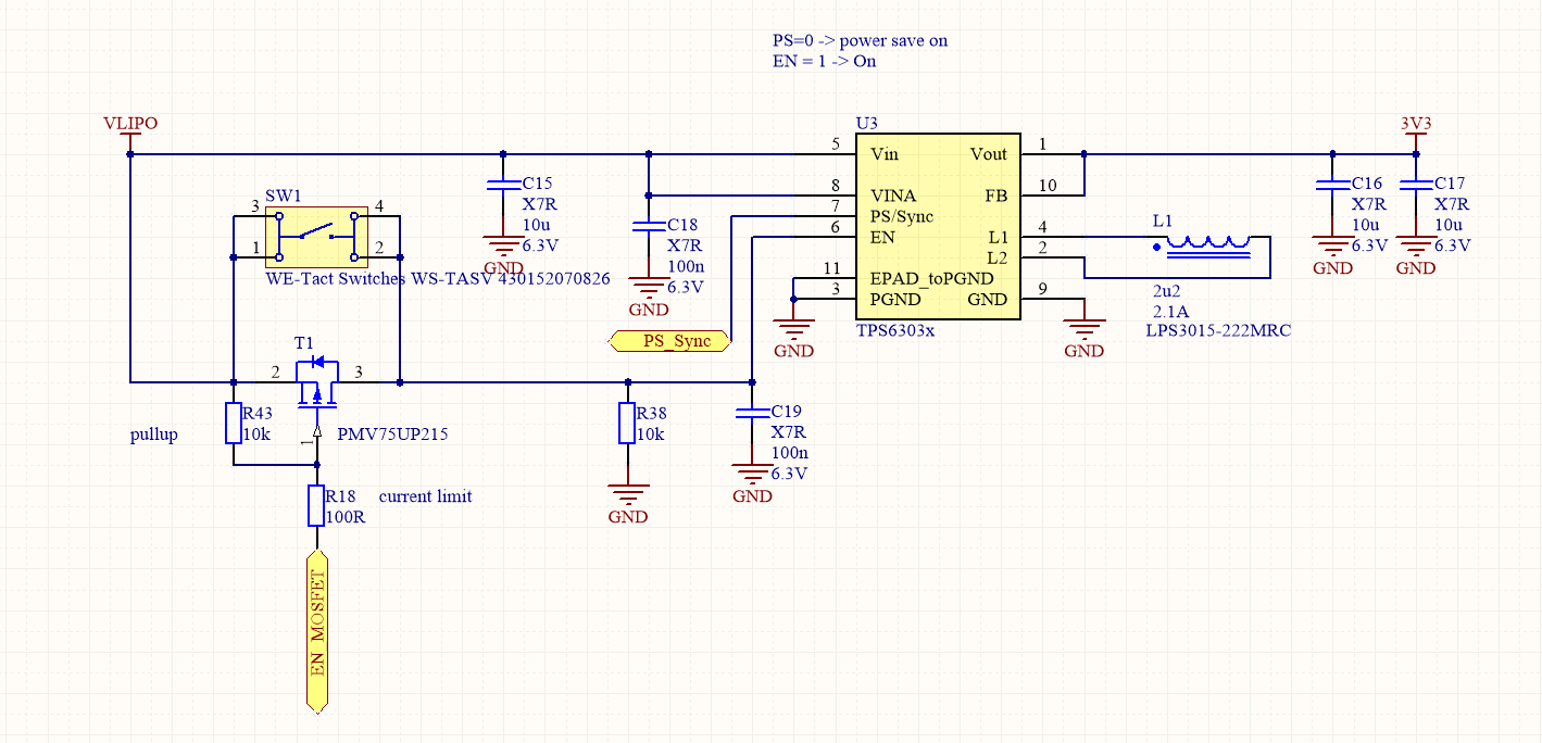
As you can see on the left side of the circuit above the self-sustaining circuit only consists of MOSFET T1, pull-up resistor R43 (and R18). R18 is not necessary but can protect the microcontroller pin connected to EN_MOSFET in the case of an overvoltage event.

Si(x) / Ci(x) (Sine integral function / Cosine integral function) in Python

The Si(x)-function (integral of the sine) in Python requires the usage of the scipy-package!

Usage:

import scipy
from scipy.special import*

(si,ci) = sici(X)

Now si and ci hold the results of the sine / cosine integral.

Make sure not to confuse the Si(x)-function with si(x) = sin(x)/x = sinc(x), the cardinal sine function. Especially German literatur often uses the expression si(x) instead of sinc(x).

Flight Computer for Hang Gliders

This project was my master’s thesis back in 2016/2017. It is based on the i.MX6 quad Linux board from http://wandboard.org

The PCB contains multiple buttons and rotary knobs for intuitive handling of the XCsoar flight software. A STM32F4 microcontroller additionally handles the signal processing of the sensors on the PCB (GPS, 9 DOF IMU, 2x absolute pressure sensor + 2x differential pressure sensors for pitot tube, lightning detection).

A high brightness (1000 nt) display is selected for proper visibility in heavy sunlight conditions. 1 nt= 1 Nit = 1 cd/m2


Activating UART2 on Wandboard Quad / Dual (iMX6 / Kernel 3.0.35 up)

The Wandboard (linux board) Quad, Dual and Singe have several UART interfaces (3.3V, not 5V tolerant) available. The official images from http://www.wandboard.org/ have UART1 activated by default because it allows you to manipulate the bootloader and to have a simple terminal access. On the wandboard baseboard UART is converted to RS232 and can be accessed via a null modem cable as shown here. Unfortunately you will get a constant output of kernel messages on this stream which might interfere with your application. However if you want to use a UART interface in your application you should either disable the kernel output on UART1 or activate and use another UART interface (like UART2). I would highly recommend you to choose the latter way since you will definitely need the kernel / boot output messages in order to make your system boot.

So here’s the deal: If you need to activate UART2 you’ll need to apply changes to the kernel & device tree and recompile it. If you want to know if activation is necessary on your system simply check if you can find a device called mxcfb2 in your /dev folder. NXP (former Freescale) decided to name the UARTs of the i.MX6 this way. The kernel output mxcfb1 (UART1), mxcfb2 = UART2, mxcfb3 (UART3, Bluetooth module connected there).

cd /dev && ls -l

If you can find mxcfb2 there your UART2 is already activated. If not you need to activate it according to this post.

Again this is only for kernel versions 3.0.53 and higher. The 3.0.53 kernel is the first to have a device tree. If you’re using a lower version of the kernel (e.g. “out of the box images” Wandboard Ubuntu 12.04) there is no device tree. If you‘re trying to work on this kernel you’ll need to apply changes to different C code source files. Anyway – if you’re using 3.0.53 and up your absolutely right here.

First step is to get the kernel sources. We will work on kernel version 3.10.53. So let’s check out the correct branch from the official Wandboard GIT repo:

git clone https://github.com/wandboard-org/linux.git -b wandboard_imx_3.10.53_1.1.0_ga

Then we can edit the device tree. I would recommend you to add a new set of pins to the file. This “pins pack” will define a set of pins which are used for UART2 communication. It is useful to define the pins RTS and CTS for hardware flow control as well. You do not need to use them but they are routed to EDM connector of the Wandboard aswell. Edit the imx6qdl.dtsi file with your favorite text editor.

 nano arch/arm/boot/dts/imx6qdl.dtsi

Add the following lines indicated with a “+” (patch style)

MX6QDL _ PAD _ EIM _ D29 __ UART2 _ DTE _ RTS _ B 0x1b0b1
 >;
};
+ pinctrl _ uart2 _ 3: uart2grp-3 {
+    fsl,pins = <
+         MX6QDL _ PAD _ SD4 _ DAT4 __ UART2 _ RX _ DATA 0x1b0b1
+         MX6QDL _ PAD _ SD4 _ DAT5 __ UART2 _ RTS _ B 0x1b0b1
+         MX6QDL _ PAD _ SD4 _ DAT6 __ UART2 _ CTS _ B 0x1b0b1
+         MX6QDL _ PAD _ SD4 _ DAT7 __ UART2 _ TX _ DATA 0x1b0b1
+    >;
+ };
};
uart3 {

This section simply defines pins of the i.MX6 processor to have UART2 alternate function. (Pins of large, complex or BGA style ICs are often called “pads”.)

Next we want to make use of the new pin set. Edit the file

nano arch/arm/boot/dts/imx6qdl-wandboard.dtsi

Again – add the lines indicated with a “+”. Other lines are only presented to enable navigation within the source code.

 status = "okay";
};
+ &uart2 {
+          pinctrl-names = "default";
+          pinctrl-0 = <&pinctrl _ uart2 _ 3>;
+          status = "okay";
+ };
+
&usbh1 {
 status = "okay";
};

After these simple steps your are ready to compile the kernel and device tree. Having finished compilation you should be able to find mxcfb2 in the /dev folder of your system.

Using terminal programmes like minicom you can simply test your UART interface.

sudo apt-get install minicom

sudo minicom -s

LVDS color problems / dimmed gray screen (Wandboard, iMX6, Ubuntu 12.04)

Enabling LVDS on my Wandboard Quad on Ubuntu 12.04 (see my blog entry here), I encountered two problems with my LVDS display.

Problem 1: Basically the settings seemed right, but there were some wrong colors everywhere (see image below).

LVDS color errorThus I decided to go for Test Card. It is freely available from Wikipedia in the linke above. Below you can see a photo of my LCD screen (upper image) and the original image as it should be (lower image).

img_2963pm5544_with_non-pal_signals

Test Card Image courtesy of Wikipedia.

Obviously the red channel is missing so I decided to check the LVDS connector and found a loose contact on my LVDS cable.

Lesson learned: Always double check your connections (e.g. using a continuity tester / multimeter). When using continuity tester make sure not to connect ground of multimeter and LCD since the testing voltage of the tester could potentially destroy the LVDS input pin and the measurement result would be wrong!

Problem 2: The screen seemed very dark and white did not represent the maximum brightness of the screen. Since I definitely knew that the backlight was at full power (no PWM activated) the problem had to be caused by the display. At this moment I had the LVDS color mode set to RGB18 (see here) which was wrong for my LCD. After setting to RGB24 the problem was solved.

Lesson learned: The LCD might work even when the LVDS color mode is set wrong. When setting RGB18 (3×6 bit) obviously the two MSB of a 24bit (3×8 bit) LVDS transmission are omitted, the display sets them to  zero. Correct settings to RGB24 resolves the issue.

Activating LVDS on Wandboard Quad (iMX6) / U-Boot / Ubuntu 12.04

Activating the LVDS in a Linux system can be quite challenging. I am a newbie to Linux – don’t blame me for these kind of trivial explanations. All explanations should apply to the Wandboard Solo and Wandboard Dual in the same way.

img_2972

My notes are describing the process for the Ubuntu 12.04. Please note it is not suitable for the Ubuntu 14.04 or higher! To be more precise it is only valid for kernel versions <=3.0.x. In kernel versions >=3.1 the device tree has been introduced to Linux. If you want to use a distribution using kernel >3.0.x you’ll need to activate LVDS in the device tree, too. (I don’t know how to do this yet). The Ubuntu 14.04 image uses kernel version 3.10 while Ubuntu 12.04 image uses kernel version 3.0.101. You can get your kernel version by typing

uname -r

in the console. Again – the description below is not complete when using kernel version >3.0.x!

I am using the Wandboard Quad (iMX6q) Rev. B1 on a custom baseboard with a LVDS connector. Anyway – the LVDS pins are routed to the GPIO expansion headers of the Wandboard Baseboard. You need to connect all the ground lines and the four differential pairs (R, G, B, Clock) each consisting of a positive and negative line. Download the schematic of the Wandboard from here and get the correct pins from there.

The LCD I use is a DLC1010AZG-T-1. The datasheet is a bit awful, but does its job.

You need to access to a RS232 interface on your debug computer. You can use a RS232-USB adapter if your computer does not have a native RS232 interface. Furthermore you need a null modem cable or adapter. These cables map the TX pin of the Wandboard (Pin 2, DSUB9) to the RX pin of the host computer (Pin 3). Same goes for the WB RX pin, it is mapped to TX pin of the host. A “normal” RS232 cable will not do the job, you need to go for a null modem cable or a appropriate adapter.

First you should use find a Linux image which is running on your Wandboard. Open your preferred terminal program (HTerm, Terra Term, …) and power up your Wandboard. The settings you need for your terminal are:

115200 baud, 8 data bits, no parity, 1 stop bit, no flow control (!), endline character <CR>

Do not use flow control! This is how the settings look like in HTerm:

hterm_settings

Power up your board and you should see a bunch of traffic there. If not – check your cables and make sure you have a booting Wandboard using a HDMI monitor.

At the beginning of the boot sequence you will see something like this in your terminal program:

U-Boot SPL 2013.10-00007-g6368217 (Mar 12 2015 – 15:38:05)…

Hit any key to stop autoboot:  3 , 2, …

During this period of time press any key on the keyboard of your host computer and make it send this including the <CR> end character. Most terminal programs automatically append a end character.

hterm_input

However if you succeeded you will have entered the U-Boot environment, indicated by

=>

Now we can work in U-Boot. We need to overwrite the boot arguments in the environment variables of U-Boot which will activate the LVDS output in the required mode for the LCD. This is done via

setenv bootargs ‘console=ttymxc0,115200 root=/dev/mmcblk0p1 rootwait rw video=mxcfb0:dev=ldb,LDB-WSVGA,if=RGB24’

“mxcfb0” is the framebuffer and the output device is the “LVDS Display Bridge” (LDB).

“LDB-WSVGA” is the resolution which is set to 1024×600 (WSVGA standard) which fits the needs of my display. You could specify the resolution manually, by replacing “LDB-WSVGA” with e.g. “1024x768M@60”.

“if=RGB24” sets the mode LVDS mode of the display. My LCD needs 8 bit each color, so “RGB24” is suitable (3×8 = 24). Potentailly RGB888 could also work, I do not know the exact differences between RGB888 and RGB24. If you know more, let me know. 

Now we need to save the environment variable permanently type in

saveenv

and perform a reboot

reboot

If you’re lucky you should see Linux penguins appearing on your display. (Give the boot process a few seconds).

img_2960

If you should see some distorted images, you probably need to adjust your color mode (RGB18, RGB666, RGB565, RGB24, RGB888) or even worse your display timing. Since this is not suitable without recompiling your kernel, I won’t cover this within this post. If you just want to adjust your color mode simply set the U-Boot environment variables again as described above and save them.

I encountered a problem with colors which turned out to be a contact problem on the LVDS connector.

Compiling XCsoar (v6.8.x) on Wandboard Quad / Ubuntu (Ubuntu 14.04.4 LTS)

This entry is about compiling XCsoar v6.8.x under Ubuntu 14.04.4 LTS on Wandboard Quad (WBQ). Theoretically this should apply to Wandboard Dual / Solo and other UNIX based operating systems, too. You will need root access.

Warning: I am not a Linux pro – in fact I am a beginner to Linux. Please correct me where ever I am wrong.

First I assume you are having the Wandboard set up and running with the official Ubuntu 14.04.4 LTS image which can be obtained here:

http://wandboard.org/index.php/downloads

Install on a Micro SD card as described in the Wandboard Quickstarter Guide. (See link above). Remember not to have the SD card mounted during copying the Ubuntu image to the SD card. Make sure you resized the SD card after putting the image on. Otherwise you won’t have enough space left for application / user / compiling.

[Optional] If needed, set your keyboard layout using

sudo dpkg-reconfigure keyboard-configuration

Of course you can also access your Wandboard via SSH.

Due to the Ubuntu images being quite outdated, we need to update our package manager’s list of known packages.

sudo apt-get update
sudo apt-get upgrade

Last step is rather time-consuming.

[Optional] If not already installed – get the GIT version control system:

sudo apt-get install git

Having GIT installed, we can now copy (“clone”) the XCsoar source code to the Wandboard.

cd /home/ubuntu
git clone git://git.xcsoar.org/xcsoar/master/xcsoar.git
cd xcsoar/

Since the “master” is always under heavy development we will use the more stable branch “v6.8.x”.

git checkout v6.8.x

Checking the branch switch can be done using

git branch -a

Branch v6.8.x should now be marked by a * or written in green letters.

Next we need to update certain submodules (mainly Boost) used by XCsoar:

git submodule init
git submodule update

In order to compile XCsoar we need GCC compiler version greater / equal v4.8. Verify this by typing

gcc -v

If the result is not greater / equal 4.8, you need to update your compiler. (This should not be an issue if you are using the official Wandboard image.)

Now we are going to install multiple required packages for XCsoar using apt:

sudo apt-get install libboost-all-dev
sudo apt-get install make \
librsvg2-bin xsltproc \
imagemagick gettext
sudo apt-get install make g++ \
zlib1g-dev \
libsdl1.2-dev libfreetype6-dev \
libpng-dev libjpeg-dev \
libcurl4-openssl-dev \
libxml-parser-perl \
librsvg2-bin xsltproc \
imagemagick gettext \
fonts-dejavu
sudo apt-get install packaging-dev
sudo apt-get install ccache

Now we are ready to compile. But first – let’s clean up the directory just in case this is not the first time you are compiling XCsoar.

sudo make clean

Since the GLX feature is not implemented functionally on the Wandboard (Vivante GPU driver problems) we need to disable GLX support (GLX=n) – otherwise the application will fail to start. Disabling GLX will automatically result in using EGL. Furthermore we are having 4 cores available to speed up compilation using option -j6. The number of compilation processes is recommended to be set slightly higher than the actual number of (physical) cores. For Wandboard Dual you would use -j3 or -j4 and for Wandboard Single you would not use the -j option. Now start compiling by typing

make USE_CCACHE=y GLX=n -j6

Building XCsoar will take approx. 15 minutes.

After successful build you can find the compiled binaries here:

cd /home/ubuntu/xcsoar/output/UNIX/bin

Start XCsoar using

./xcsoar

[Optional] If you want to install the compiled XCsoar and generate the manuals (pdf), you should run

sudo make install

Further information on the topic can be found at:

Or leave a comment (click on “leave a comment” above on the left side of the screen) …