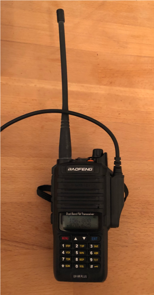
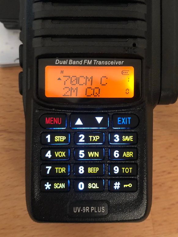
Can be ordered from ebay / Aliexpress, cost ~40€. Unknown if this model is genuine Baofeng radio or some knock-off. There seem to be different versions of the UV-9R Plus, with different keyboard color (orange brim). Some seller’s advertised data (20W TX power, 10.000mAh battery capacity) seems pretty implausible. No UV-9, UV-9R+, or similar is listed on Baofeng’s website. Cheap programming cables (CH340 based) are available and work fine for me with Windows10. Due to the completely different “waterproof” interface equipment from the popular UV-5R can not be used (headphones, programming cable, etc). Comparable to UV-5R, no frequency / channel mode button. No dedicated VFO-A/B selection button (press “EXIT” button to switch between the two selected frequencies / channels)
Programming
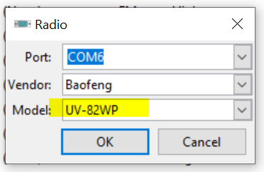
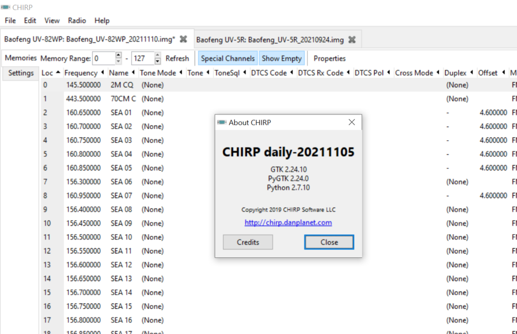
As of 11/2021 the popular free software “Chirp” can be used to program memory & settings of the UV-9R+. Selecting the “UV-9R” as radio model did not work properly. However, inputting “UV-82WP” solved the problem and let me program the channels with names and adapt necessary setting (power-up message, …)
Select UV-82WP to up- & download data from a UV-9R+ !
After switching the UV-9R+ to Channel Mode (switch off radio, hold “Menu”-button, switch on radio) I had to set “MDF-A” (upper display line, Menu-21) and “MDF-B” (lower display line, Menu-22) to the setting “NAME”. (Select “CH” for channel number and “FREQ” to display the frequency of the corresponding VFO.
This is kind of a loose data collection on BAP (for the PQ plattform) collected from various data sources and reverse engineering.
VW uses BAP (German: “Bedien- und Anzeigeprotokoll” ~ control- and display protocol) for communication between a control unit and a display unit. BAP is meant to transport data event based instead of the usual broadcast style (e.g. ECU hot-lamp = bit X in message Y, broadcasted all 10ms). Instead data (e.g. data to be displayed or menus to be built in the telephone menu) is transmitted once and updated as necessary. BAP is the successor of DDP (Display Daten Protokoll ~ display data protocol).
Everything in Volkswagen-group terminology is German, so are some of the abbrevations.
The control unit generating the data to be displayed is called “FSG” (Funktionssteuergerät ~ functional control unit). No HMI / display capability.
The control unit displaying the data is called “ASG” (Anzeigesteuergerät ~ display control unit). In PQ this is either the cluster’s display (called MFA) or the radio-navigation unit (only for certain clima-related data). Usually displays data to the user / driver (HMI), able to display data from the FSG.
Communication is always between FSG and ASG. Not ASG to ASG and not FSG to FSG.
In general different control units have different CAN-IDs they emit data from. That is no different in BAP. Certain CAN-IDs are related to BAP-traffic. In vw terms, those messages will be called something like BAP_xxx (e.g. BAP_Clima, BAP_NAVI, BAP_Compass, …) depending on their function. This is the communication channel from FSG (clima control, navigation system, compass) to the ASG (display). The communication backwards (e.g. cluster confirming displaying of data or alive-status) also has its own CAN-IDs / messages (e.g. BAP_ASG_0x, BAP_Anzeige). The FSG sends a ‘request’ to the ASG which answers with a ‘indication’ and vice versa.
Terminology: OSI-Layer1: mostly CAN (could be LIN, FlexRay, MOST, …). OSI-Layer2-4: BCL (BAP communication layer), OSI-Layer5: BPL (BAP protocol layer), OSI-Layer6: BAL (BAP application layer), OSI-Layer7: application layer (BAP functions, e.g. display text, enable symbol, …).
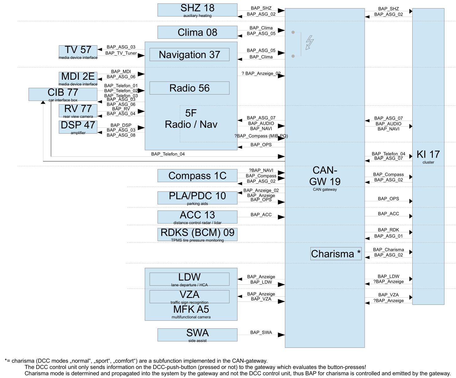
Obviously nearly all data is routed from the different CAN-bus of the car (CAN-powertrain for PDC/PLA & old ACC, CAN-comfort, CAN-infotainment, CAN-extended) to the gateway which finally routes to CAN-cluster.
Despite its alive-functions (called ‘heartbeat’) data is only transmitted event-based or based on a request by FSG or ASG. No “unasked” transmissions take place.
A BAP-message can consist of multiple CAN-messages. Each BAP-message has a BAP-header which specifies lsg_id, fct_id and op_code in addition to the BAP-message’s data.
CAN-messages
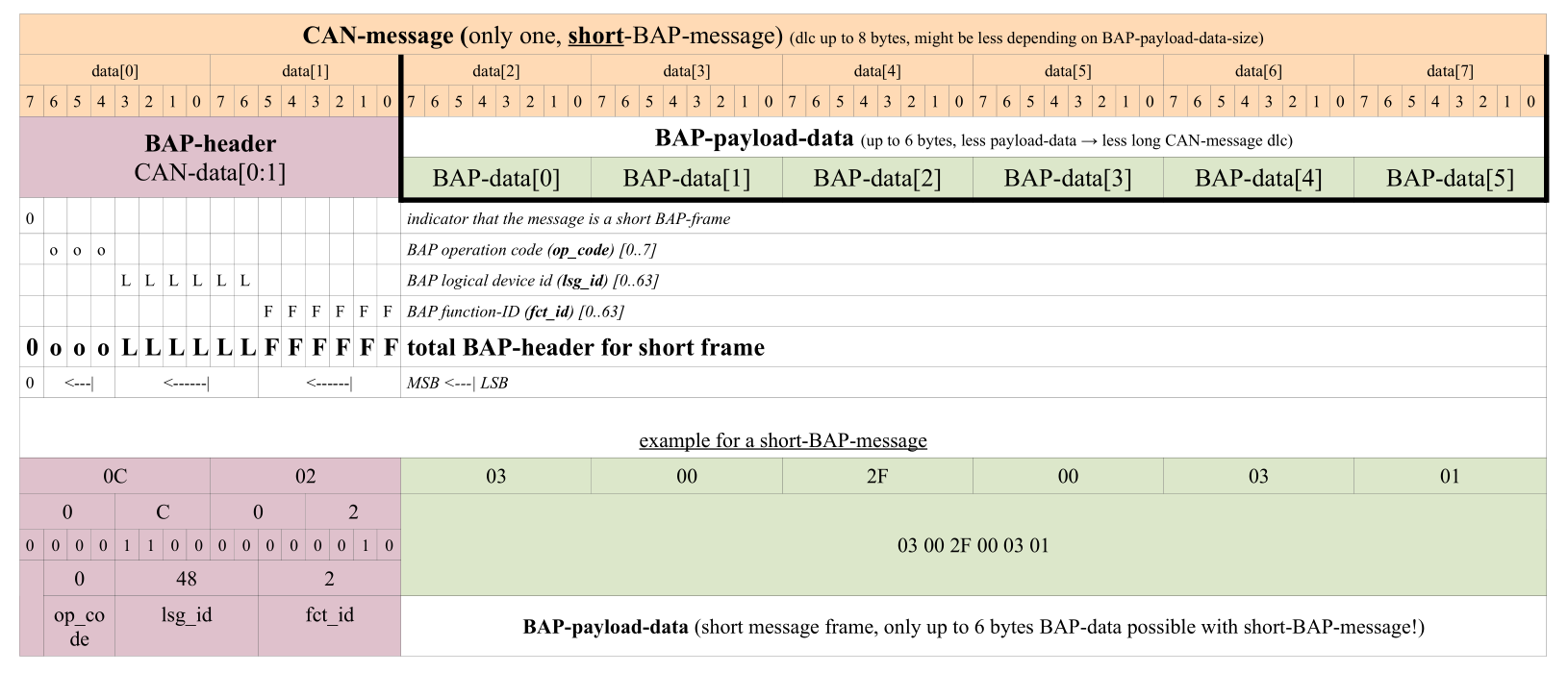
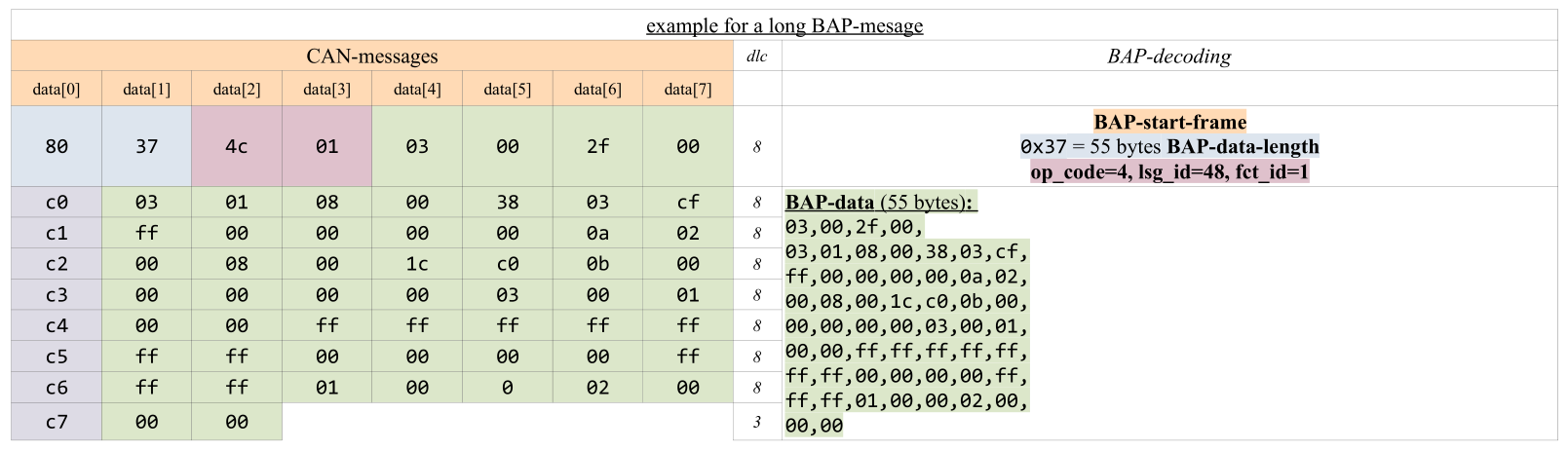
There are two types of BAP-messages: short (less or equal 6 BAP-data-bytes) or long (more than 6 BAP-data-bytes). DLC is variable.
the size of the BAP-header is always 2 bytes
BAP is big-endian (example: BAP-header is of size 16bit, e.g. using data[0] and data[1] of the CAN-message. Big-endian means that the MSB of the header is in byte0|bit7
BAP-payload-data (BAP-application-data <=6 (less or requal than 6 bytes) -> 1 CAN-message (dlc maximum = 8bytes) is enough to transmit all data. To indicate that it is a short-BAP-frame the MSB of the CAN-data[0] of the CAN-message must be clear (must NOT be set).
BAP short frame + example
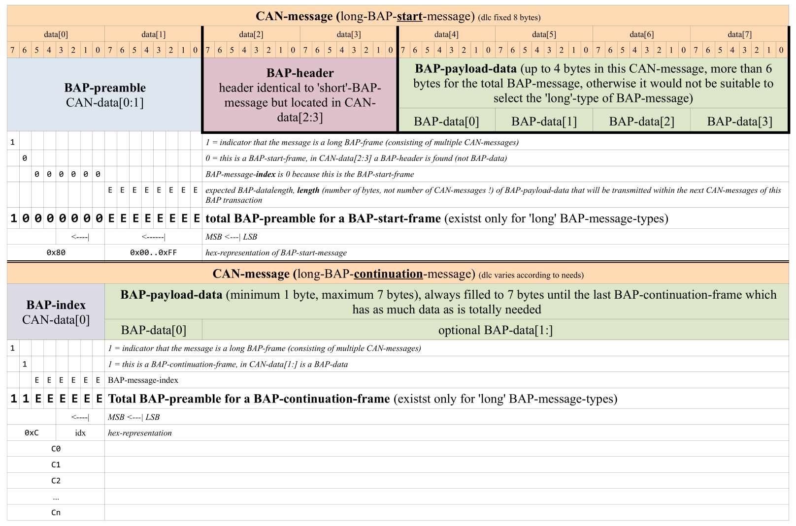
If there is more than 6bytes of BAP-data to be transmitted, the BAP-message must be split into multiple CAN-messages. The first CAN-message of this BAP-message is special, since it announces the amount of data to be expected (BAP-preample) as well as the BAP-header. The following CAN-messages have a simple counter (BAP-index) plus the BAP-data. DLC is always according to needs.
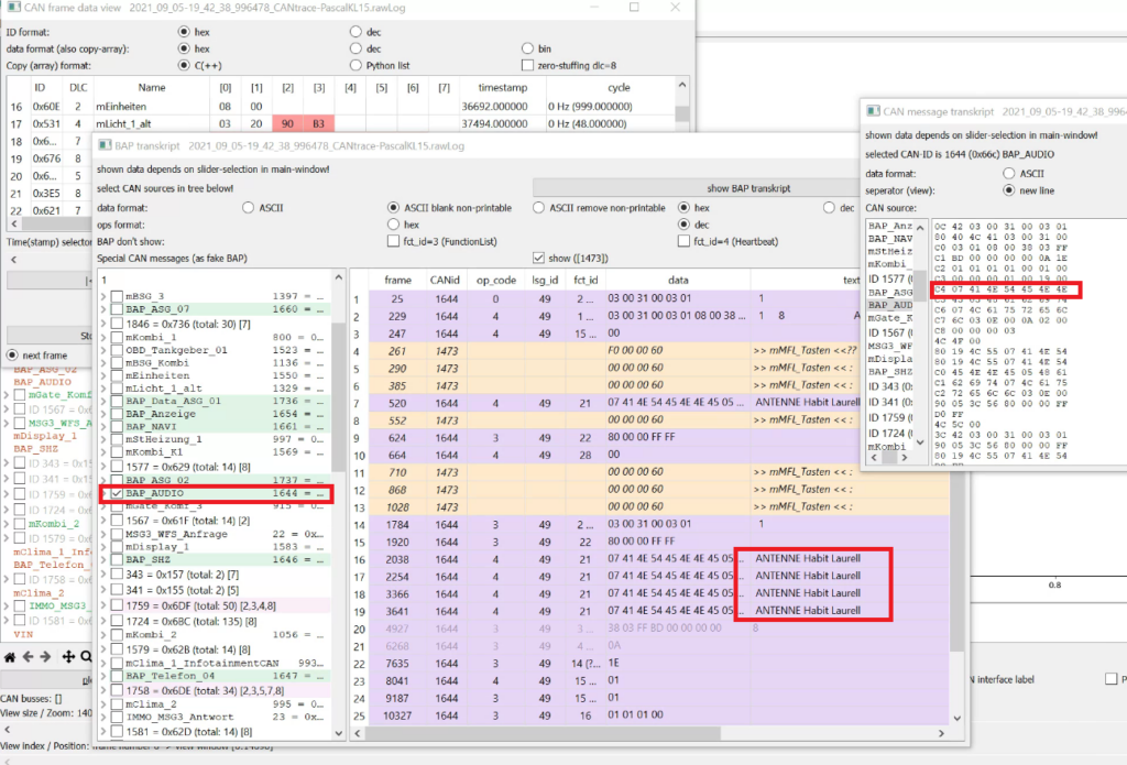
In the screenhot below you can see a decoded BAP-message which shows the radio station (“ANTENNE”) and the currently played song name (“Habitt” by “Laurell”) in the cluster’s main display, audio tab. Note that the screen is switched back and forth multiple times and only radio-BAP-information is shown in this CAN-trace which covers round about 30 seconds in total. That is why you see multiple occurences of the station-information. It is because data is always transmitted as soon as the audio-tab is opened.
list of known BAP-channels with corresponding CAN-ID
BAP communication
Inside the BAP system each control unit has (at least) one so called logical-ID “lsg_id” (logische Steuergeräte ID ~ logical control unit ID) which is partly derived from the CAN-message’s CAN-ID. Note that most control units have multiple lsg_ids, like telephone-menu and telephone-screen have different lsg_ids.
cluster shows RDS-information only, menu like structure only for FM radio stations
49 (0x31)
BAP_SHZ
(*1)
3 (0x3)
BAP_Telefon_04
8 (0x8) 12 (0xc) 19 (0x13) 20 (0x14) 43 (0x2b)
BAP_RDKS
(*1)
4 (0x4) 7 (0x7) 8 (0x8) 12 (0xc)
BAP_ACC
(*1)
5 (0x5) 27 (0x1b)
BAP_OPS
0 (0x0) 3 (0x3) 10 (0xa)
BAP_VZA
recognized traffic signs in BAP-traffic
33 (0x21)
BAP_LDW
(*1)
25 (0x19)
BAP_SWA
(*1)
26 (0x1a)
observed lsg_ids
*1 = menu items in cluster, at least no human readable content (like menu-item-textstrings) were observed in BAP-traffic from this unit
For each lsg_id exists a individual list of function-IDs “fct_id” (Funktions-ID ~ functional ID). These function-IDs describe functions that can be applied to the (sub-) control unit. For example: list all functions, screen-data, menu-data, … . For each lsg_id exists a special (device specific) set of fct_ids. However some fct_ids seem to be standardized in the BAP standard an thus often repeat:
fct_id
name
parameter
data
0x00
0x01
GetAll
get all properties
used to synchronize the application-cache in the ASG. FSG delivers all property-values with op_code ‘StatusAll’. Parameter ‘Data’ of op_code ‘StatusAll’ contains all function-property-values in one continously segmented BAP-message
BAP_Version_major (byte), BAP_Version_minor (byte), LSG-Class (The LSG_Class_ID classifies the function catalogue uniquely because a function catalogue can occur several times with different LSG-IDs), LSG-Sub-Class, LSG-Version_major, LSG-Version_minor
information for BAP-version and LSG-version
op_codes: Get (empty), Status (data), Reset (data), HeartbeatStatus (data), Error (errorCode)
0x03
Function-List
FctList = bitfield, bytestream,
list of supported BAP-functions
This bitfield indicates the support of a certain function during runtime.
op_codes: Get (noParam), Status (FctList), HeartbeatStatus (FctList), Error (errorCode)
this message contains the time betweent two heartbeat-messages. The parameter ‘HeartBeatTime’ * 100ms = time in unit ‘milliseconds, ms’. If a heart beat error occurs for a BAP-connection, it is reported on function HeartBeat (0x04)
op_codes: Get (noParam), Status (HeartBeatTime), HeartbeatStatus (HeartBeatTime), Error (errorCode)
with the parameter ‘OP-State’ this function announces the operational state of the FSG
op_codes: Get (noParam), Status (OP_state), HeartbeatStatus (OP_state), Error (errorCode)
The op_code (operation code ID) indicates the type of operation which is to be applied to the “fct_id-lsg_id”-combination. This could be something like set-value, get-value, reset, …
op_codes are grouped in function classes. Each function class has its own values and valid op_codes.
Defined function classes:
Property: time independant value that can be read or written
Array: like property but for big amount of data (multiple elements at once, e.g. lists)
Method: time dependant action
Cache: synchronize application cache in ASG
op_codes
The “Function List” (VW internal document) defines one function class (either Property or Array or Method or Cache) for each “ID” (most probable “ID” within the “Function List” means function ID = fct_id). As a result, each fct_id only has one function class and thus only one set of valid op_codes!
All parameters transmitted via BAP shall be stored in non-volatile memory on the FSG to keep information during loss of power.
Function-IDs 1 to 4 shall not be evaluated by application if not otherwise specified
Note that each lsg_id has its own list of fct_ids and each fct_id has its own set of op_codes. Not all op_codes are valid for all fct_id! All named above are (hopefully) BAP-standardized, not any more device specific or at least the same over all BAP-participants.
Control & buttons
With displaying data, there is a need to control menus, select entries, manipulate values, etc. All this is handled by the FSG (and not via BAP). Button presses from the MFL (Multifunktionslenkrad ~ multifunctional steering wheel) or steering column stalks (up/down + OK/Reset at the wiper control stalk) are passed to the control unit (FSG) which then updates the ASG’s display. It is not entirely clear at the moment if the cluster (as main display device) also handles menus and propagates selected items or adjusted values to other control units (FSGs) (on request?).
For the multifunctional steering wheel CAN-message “mMFL_Tasten” transports the pressed button in byte[0] of CAN-message: CAN-ID 1473 (dec) = 0x5c1 (hex), cycle 100ms, dlc=4
Button codes are as follows for “normal” multifunctional steering wheel:
byte[0] hex
dec
button
0x0A
10
menu up / MFA arrow right
0x09
9
menu down / MFA arrow left
0x22
34
MFA up
0x23
35
MFA down
0x28
40
MFA OK / Reset (long press)
0x29
41
MFA back
0x1A
26
telephone
0x02
2
skip+ / right
0x03
3
skip- / left
0x06
6
volume +
0x07
7
volume –
0x2A
42
PTT / Microphone / Voicecontrol
However some more modern PQ cars have a so called “MQB-style” multifunctional steering wheel with a completely different button layout. (These also have the GRA / cruise control switches) in steering-wheel-buttons and not in the turn-indicator-stalk or 3rd stalk). For those steering wheels, the button codes are different:
byte[0] hex
dec
button
0x02
2
menuRight
0x03
3
menuLeft
0x04
4
menuUp
0x05
5
menuDown
0x07
7
OK
0x10
16
volume +
0x11
17
volume –
0x15
21
skip right +
0x16
22
skip left –
0x1C
28
telephone
0x20
32
mute
0x19
25
voicecontrol
If no multifunctional steering wheel is present, the car has buttons on the right side of the wiper stalk. Those would be “up” / “down” and “OK” ( / Reset if long pressed) which also allow for navigation through the menus. It’s most probable, that those are routed with the message mLSM_1 (CAN-ID: 705 (dec) = 0x2c1(hex) in bit LS1_MFA_Tasten from SMLS into the system.
Note that the messaging scheme for PQ vs. MQB vs. MLB (Audi only) are entirely different. Following are the VW version definitions for the different CAN-matrix (as VW names its CAN-version).
PQ: CAN matrix v4.5.x (4.x ?)
MQB: CAN matrix v5.x
MLB: CAN matrix v6.x
CAN bus
VW uses 11bit identifiers in broadcast-manner, 29bit are used for diagnostic/ISO-traffic but that is (obviously) only seen when sniffing CAN bus during a diagnostic session.
Not all bus are present in all PQ cars. Passat B6 for example only has CAN powertrain + diagnosis. Passat B7 has powertrain, infotainment, comfort, cluster, infotainment mandatory.
CAN bus requires 120Ohm termination on either side of the distributed CAN. VW does use following terminations:
CAN
speed
termination 1
termination 2
AFS private
100 kBit/s
AFS: 66Ohm
AFS module left & right (both 2.6kOhm)
powertrain / Antrieb
500 kBit/s
ECU / Motorsteuergerät: 66Ohm
ACC (3C0-radars, LIDAR), AFS, Airbag, ESP/ABS, DCC, PDC/PLA, EPS/Lenkung, CAN-Gateway, TCU/Getriebe, LWS/Lenkwinkelsensor, GearSelector/Wählhebel, Haldex: all 2.6kOhm EPB (if not on private CAN with ABS)
diagnosis
500 kBit/s
CAN-Gateway: 66Ohm
OBD-II connector
infotainment
100 kBit/s
CIB/car interface box, CAN-Gateway, Radio&Navigation, phone, SHZ/Standheizung: all 560Ohm
compass, MDI/mobile device interface, rearset audio, TV-Tuner, soundsystem: all 5.6kOhm
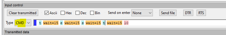
HTerm (here 0.8.5) has some special functions which can be entered selecting “CMD” (marked yellow in screenshot) and typing.
In above screenshot you can see the characters “test” followed by <CR> being transmitted with 15ms delay between each char.
delay (e.g. between characters) in milliseconds (approx.). Accuracy might vary:
wait=100
controlling pins:
dtr=1
rts=0
multiple commands can be seperated using semicolon (;) e.g: dtr=1; rts=1; wait=20; dtr=0; rts=0; and can be mixed with ASCII/HEX/DEC/BIN according to the dropdown-box / combobox.
To include a *.m file (like test.m) at the location in the file simply use the filename without *.m in the code. E.g. to include “test.m” simply put “test” into the code.
Matrices & Vectors
m x n = column x row = Zeile x Spalte
a = [1;2;3] # vector 3×1 (vertical) b = [1,2,3] # 1×3 (horizontal)
a = [1;2;3] # vector 3×1 (vertical) b = [1,2,3] # 1×3 (horizontal)
c = [ 1,2,3,4; 1,8,5,7; 1,8,6,8; ];
r3 = c(:3); # select 3rd row
Filter, find and concanate
b = find( c(:2)==8 ) # return all values from 2nd row of c where value is 8
C = [A,B] # horizontal_concanation C = [A;B] # vertical concanation
In many cases of a CNC mill, the stepper motors are controlled using the parallel port of a computer (LPT port). The CNC software toggles the pins (step & direction) for each axis according to the needs of the desired toolpath (G-code). The LPT port solution is the most simple and cheap way. One problem is latency and jitter of the software pin toggle which must be performed in realtime (synchronizing of multiple axes). Usually, LinuxCNC will take care of this problem although the result is not optimal (performance problems etc.)
Another problem of the LPT port is the undefined state and behavior during the boot of the computer. If you switch on your CNC mill usually the stepper motor driver is immediately activated. During the boot sequence of the controlling computers, some LPT pins are toggled or are in an undefined state. This might result in undesired steps and thus undesired motion of the CNC mill. In order to prevent this behavior, some stepper motor controllers have a built-in charge pump. This charge pump requires a defined squarewave signal at a specific LPT pin to enable the stepper motor controller. If this charge pump signal is missing the stepper motor driver won’t perform any motion (steps). The signal is only generated when the CNC software (here LinuxCNC) is running properly and no emergency stop condition is met. During the boot of the operating system the LPT pins might toggle or be undefined but the condition for the charge pump good won’t be met and thus no steps will be performed.
I am using the “Tripple Beast” stepper motor controller by Benezan Electronics which has charge pump functionality but the information provided here applies analogous to other motor controllers, too. In order to use the charge pump (sometimes called watchdog) on the Tripple Beast jumper 2-1 needs to be removed. The square wave signal (10kHz … 100kHz) is expected on LPT pin 16. Please refer to the manual of your stepper motor driver for the exact specifications of your charge pump.
If you’re setting up LinuxCNC you probably will be using the “Stepconf Wizzard”. During setup, you can specify the output pin of the LPT port for the charge pump. In the drop-down menu of the pin (for me it’s pin 16) select “charge pump”. This will route the charge pump signal to the desired pin in the LinuxCNC HAL.
Unfortunately, some manual changes in the HAL file are required which can not be done in Stepconf Wizzard. Please note, that the following manual changes will be overwritten every time you perform Stepconf Wizzard! In general it’s strongly recommended to backup the settings files for each LinuxCNC profile before changes or Stepconf Wizzward. Probably a (local) git repository is a suitable solution (fast revert and good diffs due to text based settings).
Navigate to the HAL file of your machine (*.hal) and open it with a text editor (e.g. “Mousepad” in LinuxCNC environment).
Completely remove the line
net estop-out charge-pump.enable iocontrol.0.user-enable-out
Add the following line instead
net estop-ext => charge-pump.enable
After that you should see a squarewave output on the desired pin (no emergency stop must be active in LinuxCNC). In my case (Tripple Beast stepper motor controller) there is a “charge pump OK” LED which will light up green when a valid charge pump signal is detected.
Please note that the frequency of the charge pump signal (“charge-pump.out”) is the frequency of the LinuxCNC base thread. If the frequency is too high to meet the specifications of your charge pump you can use a divided by 2 (“charge-pump.out-2”) or divided by 4 (“charge-pump.out-4”) signal. (See LinuxCNC documentation). Frequencies higher than those of the base thread of course can not be achived.
rfft:
One-dimensional Discrete Fourier Transform (DFT) for real input.
function rfft = rfft(a)
ffta = fft(a);
rfft = ffta(1:(floor(length(ffta)/2)+1));
end
irfft:
Inverse of the Discrete Fourier Transform (DFT) for real input.
function irfft = irfft(x,even=true)
n = 0; % the output length
s = 0; % the variable that will hold the index of the highest
% frequency below N/2, s = floor((n+1)/2)
if (even)
n = 2 * (length(x) – 1 );
s = length(x) – 1;
else
n = 2 * (length(x) – 1 )+1;
s = length(x);
endif
xn = zeros(1,n);
xn(1:length(x)) = x;
xn(length(x)+1:n) = conj(x(s:-1:2));
irfft = ifft(xn);
end
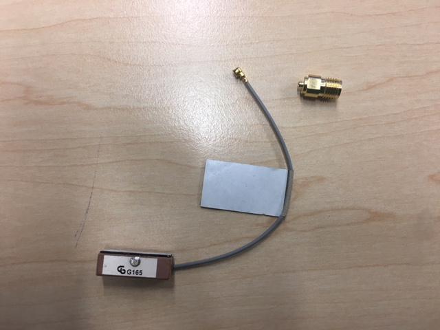
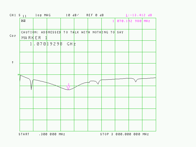
Some time ago I ordered a lot of (cheap) and small GPS patch antenna from Aliexpress.
DUT:
I was very interested in the resonant frequency so I decided to connect it to my HP8753C to evaluate the match.
Result:
Minimum S11 -13.4 dB (VSWR: 1.544:1, reflection coefficient gamma: 0.214) at approx. 1070 MHz
Antenna resonant peak far off GPS L1 center frequency (nominal 1575.42 MHz). Usually, a sufficient ground plane is required for patch antennas, but these usually shift the resonant frequency to lower values.
Nevertheless the match looks better than 10dB at the 1575.42 MHz which is sufficient
Side Note:A good match does not necessarily lead to a “good antenna”. Although a good match is a basic requirement for all energy being transported from (and to) the antenna it is not guaranteed that the energy will be radiated in an effective way. S11 (or VSWR) only quantifies the amount of energy being reflected back from the antenna into the transmitter. It is up to the antenna (material and geometry) to efficiently radiate the delivered energy. Just think of a dummy load as an extreme of this phenomena: Nearly all energy is transferred (very good match, S11 minus many dB) but nearly nothing is radiated. Beside impedance mismatch losses, ohmic conduction losses (copper etc.) and mostly dielectric losses of surrounding material (like FR4 etc.) massively degrade antenna efficiency. The belonging measure is called “antenna efficiency” mostly given in %. (For RX operation the same applies analogous due to the antenna reciprocity theorem).
Equipment:
HEWLETT PACKARD 8753C, SW: 4.02
HEWLETT PACKARD 85047A
APC-7 – SMA (f)
SMA (f) – U.FL (m) MULTICOMP MC000984
RG 58A/U 0,5m SMA (m) – SMA (m)
Kirkby Microwave 85033, ‘50Ω SMA Calibration & verification kit’