GIT cheatsheet

init repository

git init <repository-name> --bare

submodules

git checkout <commit-id>
git submodule deinit --all -f
git submodule update --init --recursive

Problem fixing

$ git status
fatal: index file smaller than expected
$ rm .git/index
$ git reset HEAD .
$ git status

detached head

if no changes have been made

$ git checkout -

(checks out the last checked out branch). Alternatively check out the branch again (e.g. git checkout master)

VW CAN and LIN (PQ plattform)

Note that the messaging scheme for PQ vs. MQB vs. MLB (Audi only) are entirely different. Following are the VW version definitions for the different CAN-matrix (as VW names its CAN-version).

  • PQ: CAN matrix v4.5.x (4.x ?)
  • MQB: CAN matrix v5.x
  • MLB: CAN matrix v6.x

CAN bus

VW uses 11bit identifiers in broadcast-manner, 29bit are used for diagnostic/ISO-traffic but that is (obviously) only seen when sniffing CAN bus during a diagnostic session.

Not all bus are present in all PQ cars. Passat B6 for example only has CAN powertrain + diagnosis. Passat B7 has powertrain, infotainment, comfort, cluster, infotainment mandatory.

CAN bus requires 120Ohm termination on either side of the distributed CAN. VW does use following terminations:

CANspeedtermination 1termination 2
AFS private100 kBit/sAFS: 66OhmAFS module left & right (both 2.6kOhm)
powertrain / Antrieb500 kBit/sECU / Motorsteuergerät: 66OhmACC (3C0-radars, LIDAR), AFS, Airbag, ESP/ABS, DCC, PDC/PLA, EPS/Lenkung, CAN-Gateway, TCU/Getriebe, LWS/Lenkwinkelsensor, GearSelector/Wählhebel, Haldex:
all 2.6kOhm
EPB (if not on private CAN with ABS)
diagnosis500 kBit/sCAN-Gateway: 66OhmOBD-II connector
infotainment100 kBit/sCIB/car interface box, CAN-Gateway, Radio&Navigation, phone, SHZ/Standheizung:
all 560Ohm
compass, MDI/mobile device interface, rearset audio, TV-Tuner, soundsystem:
all 5.6kOhm
cluster / Kombiinstrument500 kBit/sCAN-Gateway: 66Ohmcluster: 2.6kOhm
comfort100 kBit/sBCM, CAN-Gateway, clima: 560Ohm
driver-door, passenger-door: 1kOhm
trailer, Multifunktionssteuergerät, SMLS/steering column electronics, memory driver seat:
all 5.6kOhm
EPB private / parking break 500 kBit/sEPBABS/ESP (not MK60EC1)
SWA / side assist private500 kBit/sside assist masterside assist slave
extended500 kBit/s? CAN-Gateway ?
probably 66Ohm ?
MFK/multifunctional camera, SWA/side assist, ACC (post 3C0-radars like 3AA, 7N0)

“private” indicates a private CAN between control units. Private means that the CAN is not routed to the CAN-Gateway.

some abbreviations are more German than others:

  • AFS = Advanced Frontlight System
  • DCC = Dynamic Chassis Control
  • TCU = Transmission Control Unit = GSG = Getriebesteuergerät
  • LWS = Lenkwinkelsensor = steering angle sensor
  • BCM = Body Control Module = BSG = Bordnetzsteuergerät
  • SMLS = Schaltermodul Lenksäule = steering column electronics
  • EPS = Electronic Power Steering
  • SWA = Spurwechselassistent = lane change assist
  • EPB = Electronic Parking Brake = elektronische Parkbremse

LIN bus

speed 19,2 kBit/s

nameparticipants
BCM-LIN / BSG-LINRLS/rain-&lightsensor, front wiper
Tür-LIN / doorback doors
SMLS-LIN / steering wheel electronicsMFL/MFSW multifunctional steering wheel
DWA-LIN / alarmalarm horn, sensors overhead (?)
Dach-LIN / roof

Higher level protocols

BAP

DDP (probably not used in PQ, clusters with red color dot matrix display)

TP2.0

HTerm commands / CMD / special functions / delay / wait

HTerm (here 0.8.5) has some special functions which can be entered selecting “CMD” (marked yellow in screenshot) and typing.

In above screenshot you can see the characters “test” followed by <CR> being transmitted with 15ms delay between each char.

delay (e.g. between characters) in milliseconds (approx.). Accuracy might vary:

wait=100

controlling pins:

dtr=1

rts=0

multiple commands can be seperated using semicolon (;) e.g: dtr=1; rts=1; wait=20; dtr=0; rts=0; and can be mixed with ASCII/HEX/DEC/BIN according to the dropdown-box / combobox.

Octave cheatset

File opening

clear all;
clf;

File operations

To include a *.m file (like test.m) at the location in the file simply use the filename without *.m in the code. E.g. to include “test.m” simply put “test” into the code.

Matrices & Vectors

m x n = column x row = Zeile x Spalte

a = [1;2;3] # vector 3×1 (vertical)
b = [1,2,3] # 1×3 (horizontal)

a = [1;2;3] # vector 3×1 (vertical)
b = [1,2,3] # 1×3 (horizontal)

c = [
1,2,3,4;
1,8,5,7;
1,8,6,8;
];

r3 = c(:3); # select 3rd row

Filter, find and concanate

b = find( c(:2)==8 ) # return all values from 2nd row of c where value is 8

C = [A,B] # horizontal_concanation
C = [A;B] # vertical concanation

for concanation can use:

horzcat (array1, array2, …, arrayN)
vertcat (array1, array2, …, arrayN)

Plotting

fig1 = figure(1);
hold on;
title (“Titel”);
xlabel (“x-axis”);
ylabel (“y-axis”);
grid on;
grid minor on;
box on;

plot(x, y, “+”, “markersize”, 10, ‘color’, ‘red’); # markers only
# to add line connecting markers -> use linestyle

legend(‘S11′,’S22’, “location”, “southeast”)
hold off;

Vertical & Horizontal lines

plot([x,x],[0,8], “linestyle”, “–“); # vertical line at x
plot([0,8],[y,y], “linestyle”, “–“); # horizontal line a y

Plot to pdf export

print (fig1, “my_pdfname.pdf”, “-dpdflatexstandalone”);
system (“pdflatex my_pdfname”);
open my_pdfname.pdf

Strings

str_result = strcat(str1, str2);
str = num2str(my_number)

Self-sustaining circuit using P-channel MOSFET

The circuit below shows a simple but effective way to power activate a (DC) device by pressing a button. The device can be completly switched of electronically (e.g. by a microcontroller). (Switch SW2 if only shown to demonstrate the operation principle of the circuit.)
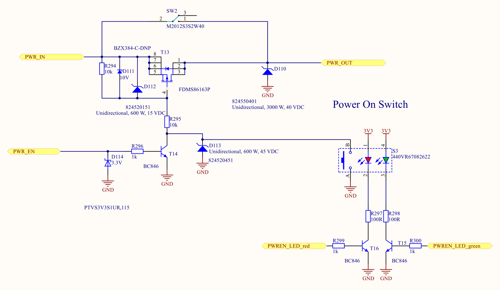
Depending on the selected P-channel MOSFET T13 the circuit can handle voltages bigger of more than 60V and currents of several tens of amperes.

The same functionality could be achieved by a relay at the expense of volume (relay is much bigger) and power consumption (~100mW or more). Especially in a battery powered portable application, there is no way for a relay.

Circuit description

Power enters the schematic at the PWR_IN port (top left). In OFF-state the MOSFET handling the power (T13) is blocking current from its source to drain. Please note the body diode of the MOSFET is in reverse to the current flowing from PWR_IN to PWR_OUT when MOSFET is conducting. In the OFF-State the gate of T13 is pulled to the PWR_IN voltage level via pull-up resistor R294 thus keeping the MOSFET not conducting. The value of R294 is selected to keep safe operation at minimal losses when the gate is pulled low.

To activate the device the user will press the activation switch S3 which closes the contacts A-B and pulling the gate of T13 to GND. As soon as the gate-source voltage at the gate of the MOSFET drops below Vgs_th (threshold voltage see the datasheet of your preferred MOSFET) T13 will start conducting. As current flows from PWR_IN to PWR_OUT a microcontroller connected to PWR_EN can boot and then control the bipolar NPN transistor T14 which will pull the gate towards GND, too. As the microcontroller starts to work it immediately needs to output high level (3,3V or 5V) to T14. After this, the button can be released by the user. The sequence to power a microcontroller should take less than 1ms.

Remaining components are mostly protecting the MOSFET and the microcontroller pin. One big problem with this kind of circuit is the limited gate-source voltage of most modern MOSFET. The majority of them will take permanent damage if the gate-source voltage (Vgs) is bigger than (-)20V. If you want to use this circuit in a 24V or even 48V environment Vgs needs to be limited. This is done by the zener diode D111. Across D111 there is a constant voltage drop of the zener voltage (chosen to be 10V here). At this voltage, Vgs is big enough to keep T13 fully conducting. D111 forms a voltage divider in conjunction with R295. TVS diodes D110 and D112 further protect T13 against voltage transients and act as a basic over voltage circuit (requiring a fuse elsewhere before this circuit!). D113 is used to protect the bipolar NPN transistor T14 in the case of an overvoltage event. R296 acts as current limiting resistor into T14 in order to limit the current out of the microcontroller pin. For T14 any NPN (e.g. BC817, BC547, BC548, …) should be fine. TVS diode D114 limits the current in case of a failure at the MOSFET (low impedance failure MOSFET conducting input voltage to its gate).

In order to switch the device OFF the microcontroller needs to deactivate its output pin (switch to lo-state). As a consequence, T14 stops pulling the gate of T13 to GND. The gate is charged again to input-level voltage (via pull-up resistor R294). T13 stops conducting, the circuit’s power supply is cut off and so is the microcontroller. Nearly no current is consumed by this circuit in OFF-state.

Simplification for lower voltage

If you have a supply voltage which is lower than the maximum gate-source voltage (Vgs_max) of your selected MOSFET (T13 above) there is no need for the MOSFET driver (T14), the voltage divider and zener diodes. This might be useful at USB designs etc.

As you can see on the left side of the circuit above the self-sustaining circuit only consists of MOSFET T1, pull-up resistor R43 (and R18). R18 is not necessary but can protect the microcontroller pin connected to EN_MOSFET in the case of an overvoltage event.

Si(x) / Ci(x) (Sine integral function / Cosine integral function) in Python

The Si(x)-function (integral of the sine) in Python requires the usage of the scipy-package!

Usage:

import scipy
from scipy.special import*

(si,ci) = sici(X)

Now si and ci hold the results of the sine / cosine integral.

Make sure not to confuse the Si(x)-function with si(x) = sin(x)/x = sinc(x), the cardinal sine function. Especially German literatur often uses the expression si(x) instead of sinc(x).

Flight Computer for Hang Gliders

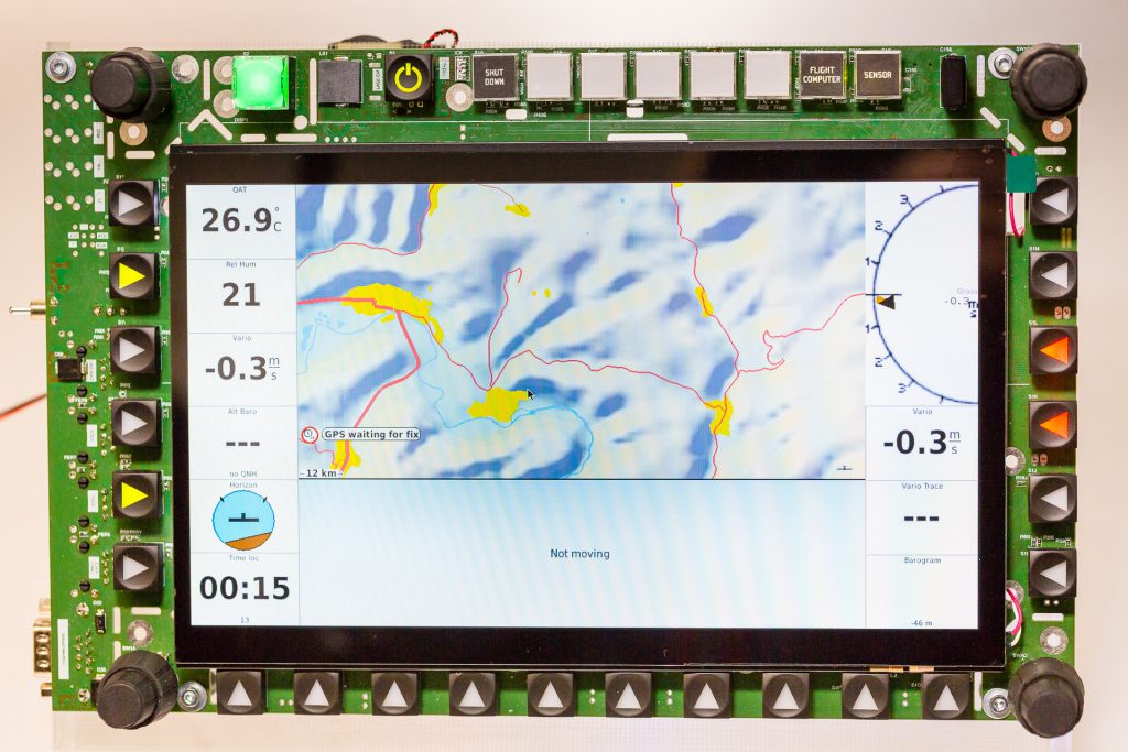
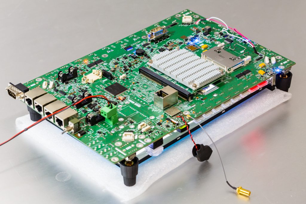
This project was my master’s thesis back in 2016/2017. It is based on the i.MX6 quad Linux board from http://wandboard.org

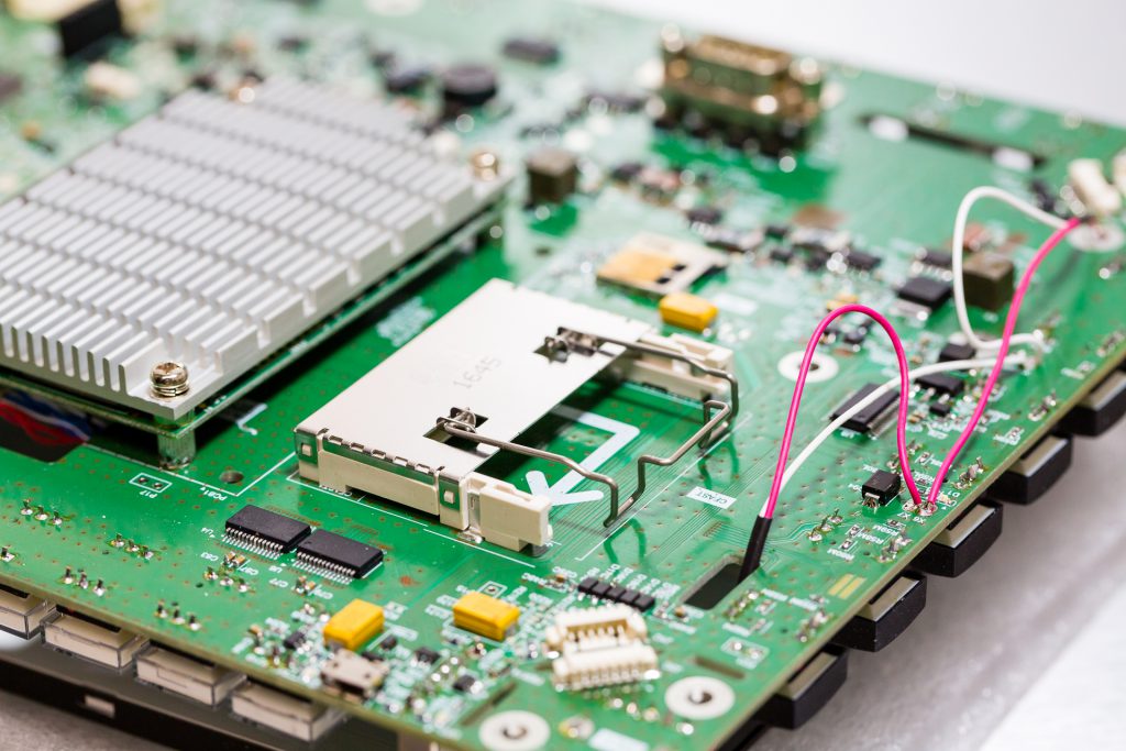
The PCB contains multiple buttons and rotary knobs for intuitive handling of the XCsoar flight software. A STM32F4 microcontroller additionally handles the signal processing of the sensors on the PCB (GPS, 9 DOF IMU, 2x absolute pressure sensor + 2x differential pressure sensors for pitot tube, lightning detection).

A high brightness (1000 nt) display is selected for proper visibility in heavy sunlight conditions. 1 nt= 1 Nit = 1 cd/m2